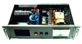
Current
limiter
This power supply is part of a larger project I am still working on, IRTS (Infra
Red Train System). It is a system which controls a miniature railway
system (Märklin 0) with a infrared remote control (like a remote
control of a television). This project has nothing to do with the
CompuTrein System but it is likely that I will use some of the designs
in both projects. Originally I named the power supply IRTS-PS (Infra Red
Train System Power Supply) but the schematic can be used in many
applications.
General
I needed a power supply of 15 V capable of delivering about 10
A, but I couldn't find a suitable solution in my electronics books. Therefore
I decided to design one myself. I had a short list of demands:
- Voltage: 15 Vdc (unstabalized)
- Current: 10 A
- Absolutely short-circuit proof
- Current-limiter (to prevent a fuse
blow)
- Voltage-cut-off after a few seconds
overload or short-circuit
- Reset-button after voltage cut-off
All this resulted in the schematic that
is shown below. The first thing I needed was a powerful transformer with
the right voltage output, a bridge rectifier suitable for the 10 A
current and a big capacitor for depressing the 100 Hz ripple. I found
these components in an old computer power supply. So now I had a power supply
capable of delivering 10 A by 15 Vdc. I also found a housing
(an old professional audio line amplifier) and a cooling ribbon for the
current limiter (total costs: nothing).

Schematic description
Now I had to design the limiter. I choose a power MOSFET (T1,
IRF9540) to limit the current because it has a very low internal
resistance (low voltage drop, low power dissipation in normal operation)
and an endless current amplification (no current needed at the gate). R6
and R7 are used as current sense resistors. The voltage difference over
R6, R7 and T1 is supplied to the open collector opamp U1a. The voltage
of the positive input is adjustable with R3. If the voltage on the
negative input goes down (current is getting bigger) the open collector
output of U1a closes. If this is the case T1 will cut off the output
voltage and the voltage difference on the inputs of U1a will be even
bigger. This prohibits that the open collector of U1a opens again. At
the same time T2 opens and the ERROR lamp LP3 lights up. The power can
only be restored if:
- The voltage between R13 and R16 (delivered
by R8) is bigger than the voltage between R10 and R11 (the open
collector of U1b is closes). This causes T3 to open and the FREE
lamp LP2 to light up.
- The RESET button SW1 is pressed.
At this point the voltage at the output
of U1a will go down and T1 will supply the output voltage again. The
voltage difference on the inputs of U1a disappears and the open
collector output opens again. T2 will shutdown and the lights LP2 and
LP3 will go out. The RESET button looses his function because the
voltage at the switch is to high now to influence the operation of T1.
Capacitor C1a is added to delay the shutdown of T1 a few seconds (RC
combination R8,R16 and C1a). This is because U1aA is added to limit the
current to 10 A. The inputs of U1aA measure the voltage over the current
sense resistors R6 and R7 (note: without T1). If this voltage gets to
high T1a will close a little, enough to reduce the output current. The
maximum output current is adjustable with R4a.
Schematic
|