DULMEN.net   Follow me on Facebook Contact DULMEN.net  

BiosLEDs@DULMEN.net

BiosLEDs
To make your miniature railway more realistic you need some moving actions in the background beside the trains. This can be done with a rotating windmill, or real moving cars. You can also create action with light e.g.: traffic lights, a welding simulating light, flashlights on a police car or ... with a running light above a movie theater. 

Both parts of the BiosLEDs

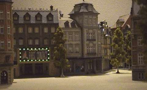
This project is about the last example. I made this project for the 
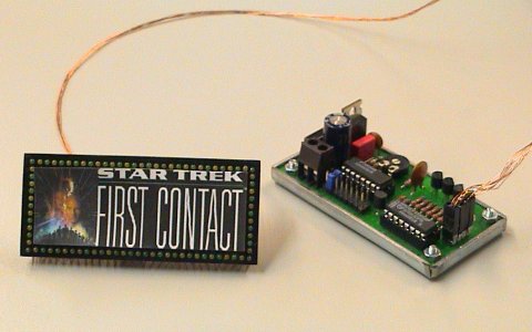
Pola "old town cinema" nr. 167 (H0 size). It has a billboard of 82x36 mm above the front doors. In order to make this project a bit realistic I had to use 1.8 mm leds (3 mm is just to big). After some calculating I came to the conclusion that I needed 84 leds. I needed an amount that could be divided by 4 because the schematic that I had in mind controls 4 channels.

Here are some features of the project:

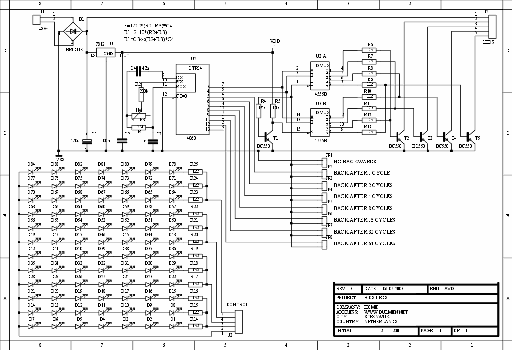
  • A 4 channel running light
  • Running speed adjustable
  • Runs forwards and backwards (preset with jumper)
  • Number of cycles before running backwards adjustable (preset with jumper)
  • Maximum current per channel 100mA (open collector, no short circuit protection)
  • Suitable for AC and DC systems (± 16 V)

If this is something for you I have to give one warning: putting 84 leds on a very small pcb and connecting them with thin copper wires is a hell of a job !

 
Schematic
Click the schematic to view the full size
 
The schematic starts with a power supply build around U1 (7812). The bridge rectifier (B1) ensures a DC voltage on the input of U1. The voltage regulator U1 ensures a 12 V output voltage for the control circuit. The leds are driven directly by the output voltage of B1 (the 12 V output from U1 was to low).
The heart of the circuit is U2 (CMOS 4060: 14-stage binary counter and oscillator, see 4060 datasheet). The clockpulse input circuit (C3,C4,R1..3) is adjustable between 8 and 48 Hz (note the RC oscillator rules above U2 in the schematic). Because the outputs of a binary counter behave as a frequency divider and the first output (pin 7) is the third divider the output frequency is adjustable between 1 and 6 Hz. Outputs 3 and 4 (pins 7 and 5) are used as the input signal for U3a (pins 2 and 3) which is a demultiplexer with 4 outputs. Every time that pin 7 from U2 changes from high to low or from low to high another output from U3 becomes active. The outputs from U3a activate transistors T2..5 which each drives 3 chains of 7 LEDs.
This was all that i had in mind before i started, but i still had half of U3 which had no function. Therefore i added T1, R4, R5 and the jumpers (JP1..8). T1 inverts the enable signal for U3a/U3b coming from output 5..12 (selectable with a jumper at JP1..8) from U2. Each time this outputs changes the other half of U3 is activated. Because the outputs of U3b drive the transistors T2..5 in a different order than the outputs of U3a the LEDs run backwards.

BiosLEDs running

 
This page is under construction !!!